Home > Techtalk > Engelstalig > Phantom Supply
Phantom Supply
This is a very simple design for a phantom supply. This design will work with microphones that have no problem with the phantom supply being only 15V. It also has to be noted that, at high SPL, distortion can become intolerable (totally depending on microphone design). In that case, the phantom supply voltage has to be increased.
The official Phantom supply is as follows: 48V, fed through 2 resistors, each 6k81 in value. They have to be matched within 0.4%. Generally we use 0.1% resistors (or select a few resistors from a 1% tolerance batch using a DVM).
Now since the question was for a simple phantom supply, fed by batteries, the choice was made to use 2 9V batteries (since a lot of microphones can be run from phantom voltages as low as 10V). Another option would have been to use an array of batteries until the 48V criterion is met. This however means a bank of 5 batteries. A final option would have been to use a step-up converter. This however would result in a schematic which is FAR from simple.
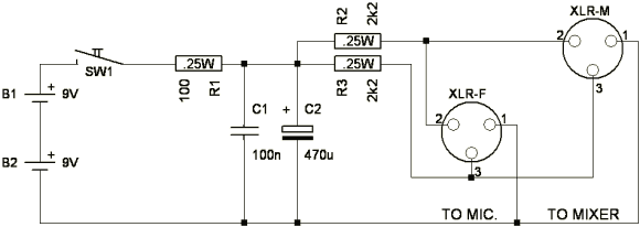
Above is the schematic of the phantom supply.
Here's the component list:
B1, B2: 9V batteries (the ones we use in our wireless mics)
SW1: Toggle switch or whatever tickles your fancy
R1: 100 Ohm (0.25W non critical)
R2, R3: 2.2 kOhm (1% or better)
C1: 100nF (film capacitor)
C2: 470uF (electrolyte, 20V or higher)
A brief explanation of the parts.
The batteries (2 x 9V, B1 and B2) supply the device with the needed voltage. The switch allows the user to turn the phantom supply on and off (to safe battery life). If this is not needed, the switch can simply be omitted. The 100 Ohm resistor (R1) is used to reduce the turn-on current. C1 and C2 make sure the power supply has a low impedance. C1 is a 100nF (or close) film capacitor, C2 is an electrolyte (20V rating at least, be aware of the polarity!). Absolute values are non critical. R2 and R3 couple the phantom voltage to both the positive and negative leg of the balanced connection. R2 and R3 are the only critical devices in the schematic and need to be matched within 0.4% as to not reduce the CMRR of the balanced connection too much.
Some notes about R2 and R3. Due to the low source voltage of the phantom supply, we can not use the official 6k81 value resistors. The values used in this schematic will reduce the input impedance of the average microphone input to some 1-2kOhm total. This still is more than enough for most microphones though it might be something one should check prior to using it. IF the impedance needs to be higher, R2 and R3 can be increased in size with the side note that this will reduce the available phantom voltage to the device. Short circuit current is 18/2k4=7.5mA per leg; pretty close to an official phantom supply.
Other side notes: This phantom supply works on microphone pre-amps that are AC coupled. If the microphone pre-amp has DC coupling, a few stopper capacitors ARE required. To measure whether the microphone pre-amp is DC coupled, measure the input of the pre-amp (with nothing attached to it) with a DVM between Pin-2 and Pin-3. If the measured resistance is below 10kOhm, it's quite probably DC coupled. Otherwise it's quite probably AC coupled. Most mic pre-amps are AC coupled. Safest way to find out is to look at the schematic (if available) or look at the pre-amp circuit board.
If microphone pre-amp is DC coupled, the schematic becomes as follows:
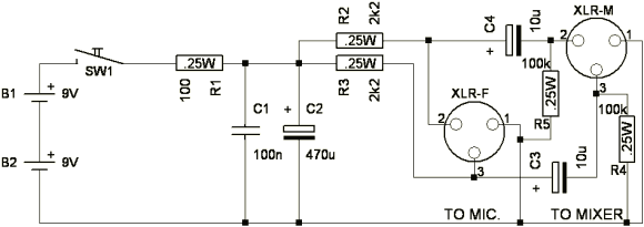
C3 and C4 effectively block the DC voltage from reaching the input of the pre-amp. Use electrolyte capacitors here with a voltage rating of at least 20V. Assuming an overall input impedance of 2k (1k per branch), the capacitors will also act as a high pass filter (1st order) with a corner at 16Hz. This is low enough. If you actually want a high pass at 80Hz (as often used on stage), you can reduce the values of C3 and C4 to 0.22uF. In that case you can also chose not to use electrolytes but use film capacitors instead. R4 and R5 are placed to correct for the parallel resistance every electrolyte has. If R4 and R5 weren't used, the output (to mixer) could contain DC if nothing was attached to it. If you then attach it to a mixer, you'll hear a very loud "pop". It is, of course, always advisable to mute the channel when you connect or disconnect a device.
Finally, for the purists out there that don't mind putting in 5 batteries (getting close to 48V phantom voltage that way), here are the component values:
R1: 100 Ohm (0.5W)
R2, R3: 6.81 kOhm (0.3W 1% or better)
R4, R5: 100k (0.25W, non critical)
C1: 100n (film capacitor 63V or higher)
C2: 470uF (electrolyte, 63V or higher)
C3, C4: 10uF (electrolyte, 63V or higher)
T-Power:
Another means of powering electret microphones is by means of "T-power".T-power (short for Tonaderspeisung, also called AB or parallel power, and covered by DIN spec 45595) was developed for portable applications, and is still common in film sound equipment. T-power is usually 12 volts, and the power is connected across the balanced pair through 180 ohm resistors. Only T-power mics may be connected to T-power inputs; dynamic or ribbon mics may be damaged and phantom powered mics will not operate properly (from Rec.Audio.Pro recording FAQ).
A schematic for a T-power supply can be found below. This schematic can (probably until proven otherwise ;-) be used to power microphones where it is important that the supplied voltage is 12V. It's biggest downside is the low maximum current it can supply (roughly 6mA before it's voltage starts to sag) and the fact that it consumes this current even when there is no microphone attached.
I'll redesign the supply soon so it incorporates a low idle current voltage regulator. Still, it should work pretty OK for at least several hours (>>10 hours).
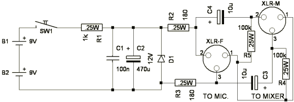
A quick explanation of the parts.
The batteries (2 x 9V, B1 and B2) supply the device with the needed voltage. The switch allows the user to turn the phantom supply on and off (to safe battery life). The 1kOhm resistor (R1) is used to reduce the current through the 12V zener diode to a maximum of 6mA. This also is the maximum supply current before the output voltage begins to sag. If this current is not sufficient, R1 can be reduced in value to a maximum of roughly 220 Ohm (thus the device is able able to supply 27mA BUT will also do that at idle (consuming 0.5W total in that case, meaning battery life will be reduced AND zener power handling needs to be at least said 0.5W)). C1 and C2 make sure the noisy behavior of the batteries is reduced. C1 is a 100nF (or close) film capacitor, C2 is an electrolyte (20V rating at least, be aware of the polarity!). Absolute values are non critical. R2 and R3 couple the phantom voltage to both the positive and negative leg of the balanced connection. It's probably advisable to use 1% resistors here though their absolute matching is not nearly as important as with the earlier mentioned phantom supply.
C3 and C4 effectively block the DC voltage from reaching the input of the pre-amp. Use electrolyte capacitors here with a voltage rating of at least 16V. Assuming an overall input impedance of 2k (1k per branch), the capacitors will also act as a high pass filter (1st order) with a corner at 16Hz. This is low enough. If you actually want a high pass at 80Hz (as often used on stage), you can reduce the values of C3 and C4 to 0.22uF. In that case you can also chose not to use electrolytes but use film capacitors instead. R4 and R5 are placed to correct for the parallel resistance every electrolyte has. If R4 and R5 weren't used, the output (to mixer) could contain DC if nothing was attached to it. If you then attach it to a mixer, you'll hear a very loud "pop". It is, of course, always advisable to mute the channel when you connect or disconnect a device.
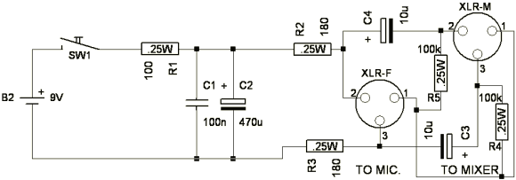
If the microphone can also be run from a 9V supply, a simpler schematic (and also less power consuming) can be used. The only difference is the absence of the zener diode, the reduction in the amount of batteries and the reduction in size of R1 (since it now only needs to reduce the turn-on current and provide a low impedance power supply (in conjunction with C1 and C2)).
Side remark: The above might contain an error here and there (and usage is fully at your own risk). If anyone sees such an error, please let me know.